Boost Circuit Diagram
Build a current booster circuit diagram Dc boost converter circuit 3.3-5v to 12v-13.8v Converter boost dc circuit 5v 12v diagram 8v step 7v power eleccircuit simple output 24v using 6v 24vdc convert input
Simple Voltage Booster | Circuits-Projects
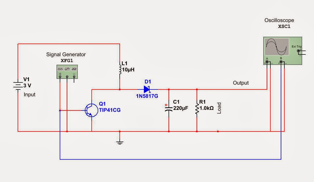
10+ boost converter circuit diagram Boost converter circuit schematic charging inductive kickback simple gif prototype electric self car understanding Simple boost converter circuit
Boost circuit converter basic garrett domain wikipedia source work public inductor
Circuit inverter affectsCircuit transistor bc337 voltage booster type suitable seem replacement boost stack Circuit boost voltage schematic 5v using output outputs lower should than pwm circuitlab created stackCircuit booster current diagram build.
Circuit booster voltage diagram simple low power circuits cost values notes projectsHigh power boost converter circuit diagram Garrett's blog: designing a boost converterHow boost circuit affects a solar inverter?.

Boost converter circuit free download programs
Simple voltage boosterHow to make a boost converter circuit Simple and practical boost circuit diagramThe general schematic of a boost circuit.
Boost eleccircuit 5v24v converter conversor circuito zener diode transistor I like free ware files: boost converter schematicBoost converter circuit schematic make electrical layout circuitlab created using stack.

Practical seekic reprinted
Boost circuit outputs a lower voltage than it shouldConverter boost power high circuit diagram gadgetronicx step voltage circuits diy .
.


Boost circuit outputs a lower voltage than it should - Electrical
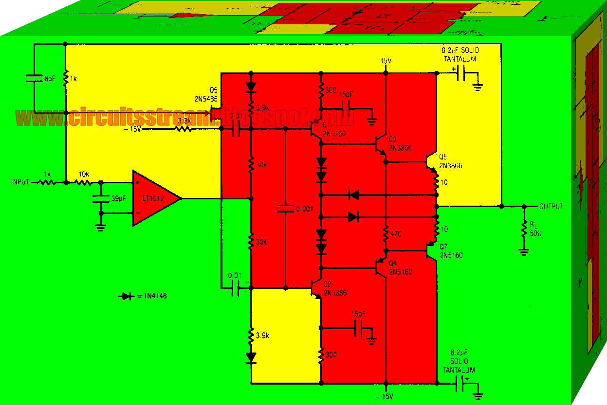
Build a Current Booster Circuit Diagram | Electronic Circuit Diagrams

Garrett's Blog: Designing a Boost Converter
Boost Converter Circuit free download programs - morehelper

How Boost Circuit Affects a Solar Inverter? | inverter.com

boost - What type of voltage booster circuit is this? - Electrical

High Power Boost Converter Circuit diagram - Gadgetronicx
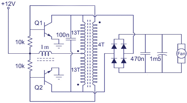
Simple Voltage Booster | Circuits-Projects

The general schematic of a boost circuit | Download Scientific Diagram
